Top Notch Info About How To Draw A Series Circuit
Electric Circuit Diagrams: Lesson For Kids - Video & Transcript | Study.com
Draw A Series Circuit That Contains One Battery And Three Resistors. - Mathsgee Science Technology Innovation Forum

18.1 Series Circuits | And Parallel Siyavula
Analysing - Janelle's Demonstration Of Standard 3 &4
What Is Series Circuit? Definition & Calculation | Linquip

How To Make A Series Circuit | Difference Between Parallel And Circuits School Project - Youtube
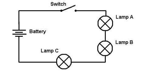
She will cover everything from wires, light bulbs, switches, and resistors.
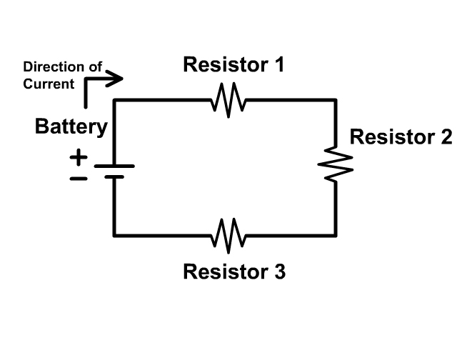
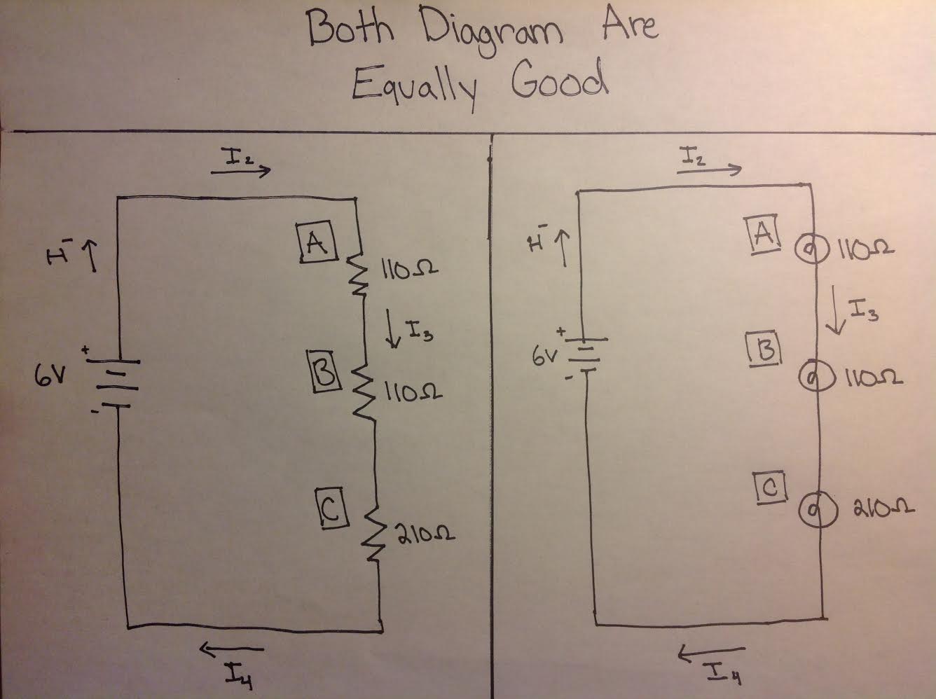
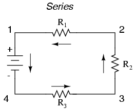
How to draw a series circuit. A series circuit in which the resistance is combined through the equation, rtotal = r1 + r2 +r3 +. Series circuits allow for electrons to flow to one or more resistors,. Series circuit let’s start by drawing the circuit pattern you see here.
Use the stencil to set the distance between the pads where the feet of the modules will go. In case of series rl circuit, resistor and inductor are connected in series, so. Draw a circuit diagram of your circuit.
Take a look at the diagram below: An led has been used in place of the bulb. To connect the second cell in.
Rlc circuit for drawing the phasor diagram of series rlc circuit, follow these steps: Examples of circuit symbols used in drawing circuits examples of drawings of a simple circuit with a bulb, cell and the switch. R1,r2,r3,.,rn is the resistance of resistors 1,2,3,.,n.
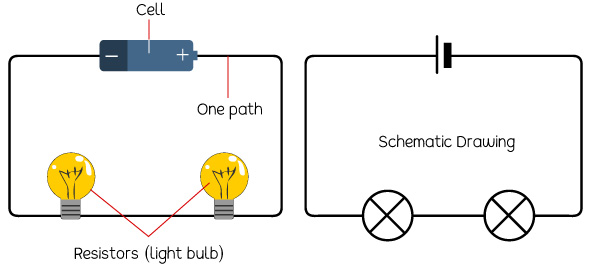
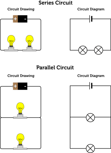
Bodechon will teach you the basic symbols used to draw electrical circuits. This has been drawn using circuit wizard software. The circuit is shown below.
A pictorial representation of the circuit : Connect another cell in parallel with the first cell. Example of a simple circuit with the switch on.
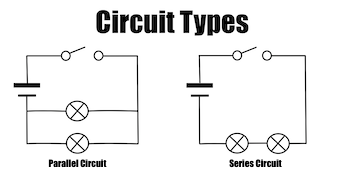
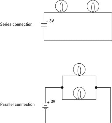
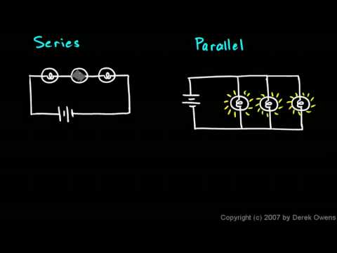
Electrical circuits can be arranged in either series or parallel. Resistor, capacitor and inductor are connected in. Rl circuit for drawing the phasor diagram of series rl circuit;
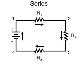
Observe the brightness of the bulb and record the ammeter reading. In case of series rlc circuit; In a series circuit, the components are arranged in a line, one after the other.
Circuits: One Path For Electricity - Lesson Teachengineering
What Is A Series Circuit?
B>electronics Projects: How To Build Series And Parallel Circuits</b> - Dummies
How Can I Draw A Series Circuit? | Socratic
Physical Science 6.5a - Series And Parallel Circuits Youtube
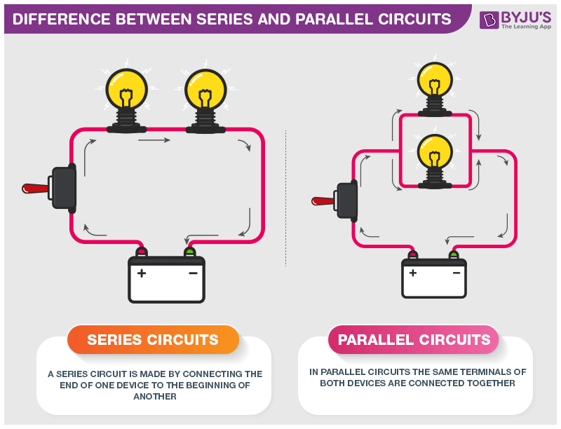
Difference Between Series And Parallel Circuits With Its Practical Applications In Real Life

How To Make Simple Series Circuit ... Try It

Series And Parallel Circuits Stock Vector - Illustration Of Lamp, Circuits: 67662763 | Circuits, Electric For Kids, Science

How To Make A Series Circuit | Difference Between Parallel And Circuits School Project - Youtube

How To Make A Series Circuit With Switch?
Andreas07: The Simple Solution Template
Electric Circuits | Ck-12 Foundation

18.1 Series Circuits | And Parallel Siyavula